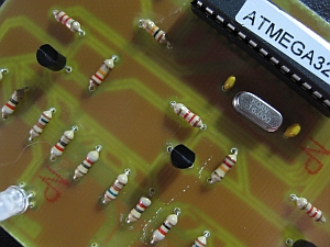
 I recently remodeled my office as I’ll be working from home full-time starting in March, it’s amazing what you can do with $1k dollars at Ikea! Anyhow, love my office setup, especially my desk but I had one nagging issue, I couldn’t see the keys of my keyboard easily when the office was dark. My wife subltly suggested I get some sort of light to put underneath my desk to illuminate the keyboard. Ah, how I love my wife and her fantastic ideas…
Obviously, I wouldn’t settle for some store bought device, I’m a self-declared “Maker” after all! After several days of tossing around ideas in my head, I decided it’d be super neato to have an RGB LED board under my desk and have it connected and powered by my computer. I’d then have some software sit in my system tray so I could control the board (colors and etc). Yeah, that’s exactly what I needed!
So, yesterday I decided I’d set out to build it with only the parts I had on hand, I’m having a baby and thusly on a very restricted hobby budget!
Since I’d be etching the board myself, I knew I’d use through hole components to make life easier and I centered the project around an ATMega328 since I wanted to use serial communication with my PC and the quickest path was to use Arduino programming language (using a FTDI cable). I also wanted to utilize some 5mm common annode RGB leds I had on hand from a previous project but I wanted at least 5 to make sure I had good illumination on the keyboard and I wanted to use PWM to allow color mixing…well, a few 2907A transistors and a dozen or more resistors later I had a schematic I could be proud of.

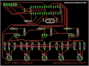
Eagle Board Layout for my RGB keyboard light
The layout of the board was easy, I had a 3″x4″ single sided copper photoetch board, so I laid all my components out to fit the whole board (I didn’t want to cut it). I also learned the hard way that small traces are a pain in the butt when etching your own boards so I set my traces to 24mil, genrously large enough to not create issues during the etch. I didn’t get any pictures of the board before it was mounted, sorry. You can always refer to the board image in the zip file attached to this post.
Once I had soldered all my components on the board, I threw in an ATMega328 micro that already had the Arduino bootloaded burned. Hooked up my FTDI cable and my test sketch worked flawlessly. Whew, nothing like going from concept to finished board with no testing to get the nerves going!
With the board testing out good, I set about coding up a C# app to control it. I had previously worked with serial comunications using C# and an Arduino which I talked about in this post so the C# code was really more about figuring out how to get a sys-tray app working as I wanted than worrying with the serial communications. I think it took me about 2 hours from start to finish to get things to a point I was happy with (nice and quick not nice and neat). I’m a developer by trade so I knew all along this would be the easiest part for me.
Well, a very quick project for me, one I’m quite proud of actually. As always I’ve attached high resolution pictures, eagle schematics, Arduino sketch and this time the Visual Studio solution in the zip below.
Drop me a note if you have any questions about this project, I think it’s a fun and easy project for folks to test out thier etching and coding skillz!
Check out the videos below to see the software and board in action!

5 Pingbacks