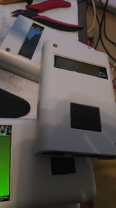
Finished monitors looking sharp in their enclosures.
In my last post I talked about an issue my company had. We couldn’t monitor our paging infrastructure from end-to-end and we couldn’t find anybody selling anything that could. Before folks start yapping about pagers, you will see them in the healthcare sector for many more years to come when it comes to contacting a doctor for a life safety issue (cardiac arrest, etc) there is nothing currently sold that is as reliable and timely in the crowded RF world of a hospital.
I had built a prototype monitoring system using one of our pagers and an Arduino paired with a Windows Service. Well, it works and it works wonderfully so I was asked to build three more. Using multiple devices ensures we don’t get false positives regarding a system outage due to the device or computer failing.
I’ve long been a fan of Adafruit and they were my first choice when I had my company order the parts needed to build out the rest of the monitoring devices. I leveraged the Arduino enclosure and the protoshield they sell and everything worked out wonderfully. I must say for a home-built gadget, they look pretty darn good and they perform wonderfully.
My apologizes for the quality of the pictures, had to use the cell….
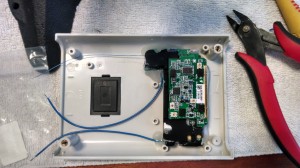
This is the back side of the Motorola pager (after the being removed from the case). The two larger wires on the battery leads and the smaller is the signal wire from the positive side of the beeper on the pager.
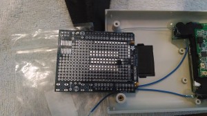
This is the protoshield from AdaFruit. Getting ready to finish wiring up the battery leads to my 1.5v regulator on the protoshield and the signal wire to the analog pin. The pager is now powered from the 1.5v regulator.
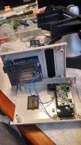
Finished the wiring. All three wires! This is a much simpler setup than the original prototype.

Leave a Reply
You must be logged in to post a comment.