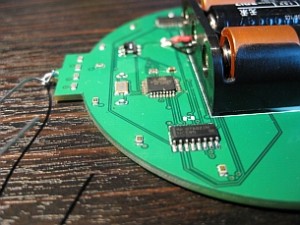
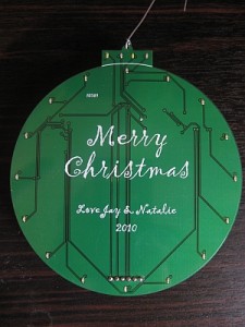
 Last year I decided to jazz up our family Christmas cards with LED power, inspired by this article. While I was totally happy with the cards I sent out, I was wanting something a bit more this year so I’ve decided to take it one step further and create Christmas ornaments for our family that will be sent with this year’s Christmas cards.
I had a few criteria that drove my design for the ornament not to mention I had a very short timeframe so simplicity was important:
1. Have the same shape as a typical Christmas ornament (it is an ornament after all).
2. Lots of LEDs, folks in my family love LED blinky things.
3. Battery powered and last as long as possible on battery.
4. Hackable. I wanted the board to be easily hacked by family and friends that were so inclined.
5. Maximize the visual appearance of the front of the board (no through-hole components), I was also going to put a Christmas message on the front in silkscreen.
After a few hours piecing together the schematic, I was pretty happy with the reChristmasOrnamentsults. Ironically when I went to start the board design I ran into a simple but problematic issue of how to evenly place the LEDs on the round board, being the true geek that I am, I wrote a C# app which you can see in the ZIP file attached to this post. It gave me the x and y coordinates for each LED given the radius, origin and degree. Being late at night when I finally got around to laying out the board, this was a true life saver!
Once I had the LEDs placed, I decided to go back and add some blue and white LEDs on the neck of the board to enhance the “blinky” factor. Skip ahead 4 more hours and I had finished the board layout. I always give myself a day or two after the board is done before I come back to it and QA the layout, saves me tons of time staring at a problem and not seeing it! My QA found several issues and once resolved I sent it off to the boys over at BatchPCB.com for fabrication.
Fabrication typically takes three weeks or more but I was nicely surprised when my boards shipped after only 7 days and being the OCD type I am, I had to assembly one of the boards as soon as they came in the mail. It took me about 3 hours to assemble the first board, I was being overly cautious and deliberate in each solder and relearning how to use my hot air rework station. The total time for the first board included soldering up my homemade ATMega TQFP programming board which I used to burn the Arduino Uno boot loader onto the ATMega chips I had leftover from a previous project. I’ll post about it in more detail later, I have a few minor tweaks to make to the design before I think I’ll be totally happy with it, but it served me well for this project.
With the boot loader loaded, the final test would be attempting to load a sketch on it using my FTDI cable. To my total elation, it loaded the sketch without issue and my blinky utopia began! I was absolutely filled with joy when those LEDs started blinking away, who knew something so trivial could be so satisfying. I learned a lot with this project and I gained some important confidence in my design and layout skills which should serve me well with my next project.
As for battery life, I’ve adjusted some of the animations so that I could eliminate having all the LEDs on for extended periods of time and found that I was able to leave the ornament on constantly and the batteries died (the board actually froze) after about 40 hours. I thought about putting in a sleep mode after 6 hours of use or something but I think I’ll pass and allow the user to just remember to shut them off, heck those inclined could do it themselves!
Well, I’m giving out the ornaments on Thursday (Thanksgiving) so that friends and family can enjoy them on their trees this holiday season, I sure do hope they enjoy them as much as I enjoyed building and designing them! Check out a video of them in action below!

December 15, 2010 at 11:17 pm
This is a really cool design, I really like it! Well done! Do you happen to have a model number on those LEDs? I’m thinking about doing a similar idea as this and would like to use small LEDs like that. I still need to work on programming it, hopefully that will come easily… Also, was the “Merry Christmas” done on BatchPCB’s end or did you add that after it came back to you?
January 6, 2011 at 4:49 pm
jakeh,
Sorry for the delay in responding, been busy with the holidays and whatnot. Anyhow, I used LNJ237W82RACT-ND from digikey.com for the red LEDs. Same 0603 footprint for all the others as well, they are “fun” to solder even with my hotair rework station, but I wanted a nice clean look on the front of the board.
I imported “Merry Christmas” artwork into Eagle and placed it on the top silkscreen layer and let BatchPCB.com do the printing with the board. Turned out really nice! The only issue I have is that they add a number on the silkscreen (I guess it’s the order number) and that distracted a bit from my design. I assume I could have reversed the design and they’d put that number on the back, lesson learned I guess.