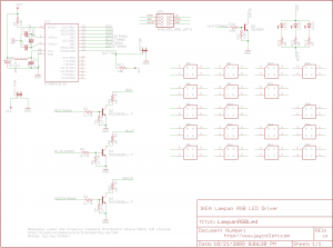
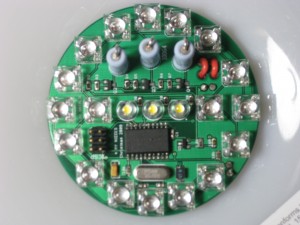
A few months ago, I saw this blog and video. The gentlemen had hacked a Lampan light from IKEA with LEDs, I was immediately enamored with the idea of building it and giving a few of them to my young nieces for Christmas. I figured they’d be far more excited about a one-of-a-kind light than a few more dolls in the ‘ole toy box.
I also wanted to further my design knowledge of PCBs as well as better understand using PWM in AVRs, until this point I’d really only played with my Arduino and a few ATTiny13s. I quickly came up with the following design to suite my requirements.
My Requirements:
1. AVR with at least 3 PWM channels. (I used the ATTiny2313)
2. Super bright RGB LEDs.
3. Warm white light for normal use, not the normal blue hued white LEDs.
4. In-circuit programmable design.
5. Fit in the base of an IKEA Lampan.
6. UL approved power source.
The lamp uses a single momentary button to switch (you need special drill bits to drill the hole in this thin plastic, trust me, check Harbor Freight for them!) between the colors and the two color mixing modes (one, I jokingly refer to as “light switch rave” and the other a slow color changing mode). My wife absolutely hates the blue hue of normal LEDs, so I knew my design would have to incorporate a few warm white LEDs in addition to the RGB LEDs, thus the 3 warm white LEDs in the middle of the board.
I got the 5mm RGB LEDs from here, highly recommended! And yes, I did use a single resistor for each color, typically a no-no in design, but the trade-off was worth it for me. I wasn’t overly concerned with exact color intensity from each LED.
Anyhow, this was a fun build and Christmas was a hit, the family loved them. I’ve attached the Eagle schematic and AVR Studio files to the post if anyone is more interested in the design.


August 9, 2010 at 12:40 pm
Lovely project. The ATtiny2313 is great. I had no trouble getting 8 channels of 8-bit PWM (multiplexed to 32) out of the ATtiny2313, with the internal oscillator instead of a crystal. http://code.google.com/p/pwmsign/wiki/Home
Did you have any trouble with the drive transistors heating up? Those power resistors really dominate the board.
August 9, 2010 at 2:01 pm
The transistors don’t even get super warm, even with hours of use. I’ve always read and I guess taken to heart that you should always select components with much higher working specs than you ever imagine you’ll need. Looking over the design, I’d like to figure out how to eliminate those resistors without increasing the size of the board…I’m gonna read through your code, this is why I love blogging about projects, I always get someone who helps me further my knowledge!
August 9, 2010 at 2:55 pm
“How do I eliminate resistors from my LED project” seems to be a recurring theme with amateur electronics enthusiasts (like me), probably because although resistors are practically free, if you don’t have one handy it’s not very handy to need one. Leave them in! I plan to use a constant current sink shift register LED driver IC instead of resistors for my next project.
August 9, 2010 at 4:16 pm
A very cool project and one I think I might have to tackle for my teenage daughters. Would you mind sharing where you had your PCB made for this project? I’m relatively new to this and not sure about how most people go about getting small order PCBs manufactured. I’m thinking Sparkfun at this point.
Thanks for providing the code and schematic.
August 9, 2010 at 4:59 pm
What is the rating on your DC transformer? Do the super bright LEDs get dimmer as they warm up?
I am working on a project with the Arduino. It is rated to output 40mA per digital output channel.
The spec on the LEDs is 400 mA with a forward voltage of 2.5v. The Aruduino will limit the amps, but they aren’t nearly as bright as they could be. I could connect them through a transistor, but then I run into power limitations. 3 x 400mA = 1.2A…more than my transformer which is rated at 1.0 amp.
I was just wondering if you ran into any power problems and what limitations you ran into.
August 9, 2010 at 7:43 pm
@ron
I had these made using BatchPCB.com (which is SparkFun’s PCB company). They are great if you only need one or two boards. I would definitely recommend them for folks just starting the process of having professionally made PCBs.
@mark_s
My transformers are 5V 2.5A. I picked them up from bgmicro.com. They were originally used as DLink router power supplies. I always hook up my prototype boards to my DMM to test the average and max current used. Since the LEDs are using PWM and very rarely are at 100% duty cycle, there isn’t as much current draw as you would think, the max for this design was like ~1A. I always double the power rating on the supply for safety, however.
The biggest design issue I had was selecting the ideal transistors to drive the LEDs…Learned alot about choosing the right transistor for your design specs.