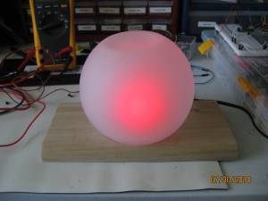
Let me start by saying I found out a few weeks ago that I’m going to be a father. This is my first child and as you can imagine I’m filled with excitement and nervous energy. Both my wife and I both agreed that we wouldn’t start actual preparations for the coming baby until the 12th week to ensure all was well (1 in 4 pregnancies end in miscarriage). I just couldn’t sit still and wait, I started reading about what to expect, how to care for a newborn, and so forth.
It was while I was reading about SIDS (sudden infant death syndrome) that I saw a few articles discussing the proper temperature for a nursery to help prevent the SIDS. The articles all agreed that cooler was better, ideally between 64 and 74 degrees Fahrenheit.
I was immediately struck by the idea of creating a visual indicator to allow both my wife and I to easily ensure the room was within this range! I grabbed up my Maker’s Notebook and starting drawing what I was envisioning. What did it look like, you ask? Keep reading, you’ll soon be rewarded with the answers you seek!
My idea was to utilize a diffused RGB LED, an analog temperature sensor (really wanted to expand my working knowledge of the ADC on AVRs) and a frosted glass sphere to create a highly visible temperature indicator. I quickly sorted through my parts bins and found most of what I would need. A quick search on eBay and a short drive to Lowe’s provided the rest.
Here’s what you’ll need to build one yourself:
1. Wooden base, use your imagination.
2. Frosted glass light shade.
3. LM335 Analog Temp Sensor
4. Atmel ATTiny45/85 micro and appropriate socket.
5. Common anode RGB LED (doesn’t have to be diffused, you can do that yourself with sandpaper).
6. Two (82 ohm) , one (150 ohm), one (10k ohm) and one (2.2k) 1/4 watt resistors.
7. A 10k potentiometer.
8. One (.1uF) capacitor.
9. A power source. I used an old Netgear router power supply. 5V regulated output at 2.0A.
10. Some wire, heat shrink tubing, Velcro and appropriate soldering equipment.
11. Firmware and schematic.
I typically breadboard all my designs then move them to PCBs once I’ve worked out all the kinks, but I had recently purchased a mini drill-press and PCB development kit from Jameco and decided the simplicity of this design would allow me to go directly to a DIY PCB (it also gave me an excuse to try my newHad to calibrate the temp sensor using the 10k pot and my Fluke with attached thermocouple.
Once done, I sat down and wrote up the firmware using AVR Studio 4. After a few more hours, I was all set to try it out. And TADAAA! A fully functioning accurate temperature indicator for the new nursery. I’ll paint the wooden base once we decide on colors for the nursery!
AVR Freaks (ADC For Newbies)
Convert Kelvin to Fahrenheit


August 6, 2010 at 4:19 pm
Thanks, nice project